Background
Stitching together images taken with a macro photography setup is not a trivial task. With some setups it is possible to use programs that are designed for microscopic images (very low distortion) like the Grid/Collection Stitching plugin for ImageJ/Fiji or the Montage all images in this layer function in TrakEM2. However, as soon as there is noticeable distortion in the images, there will be artefacts if you attempt to blend the aligned images to a panoramic image.
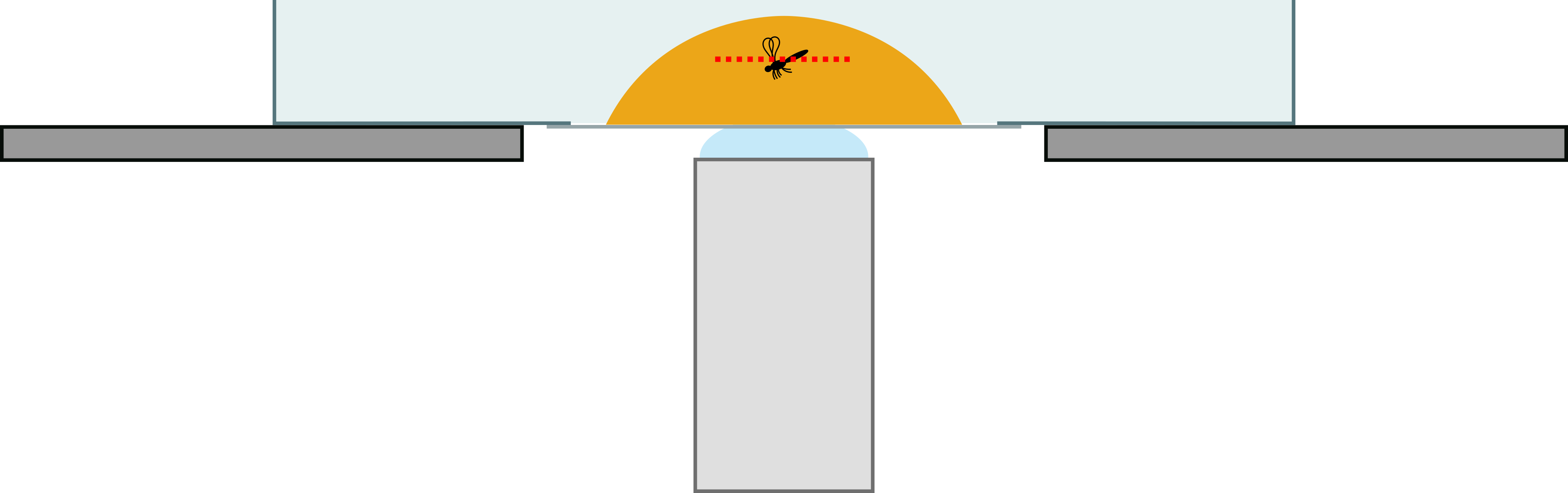
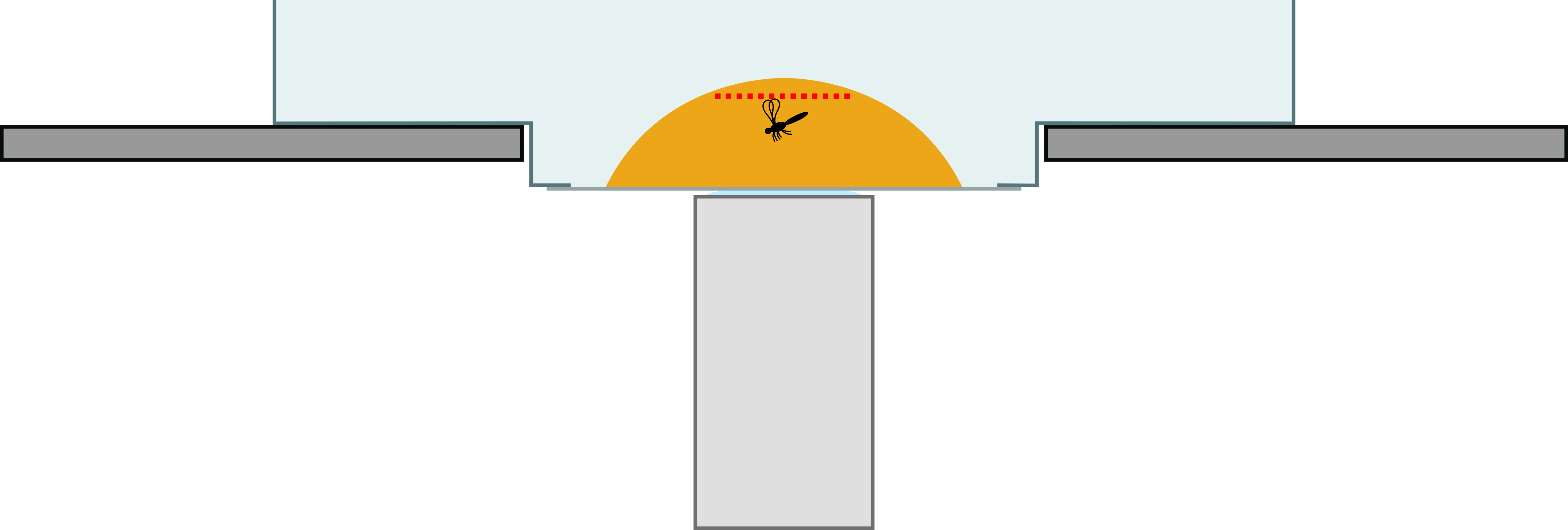
Most panorama creators take into account the distiortion of the images. However, they also assume that the panorama was recorded by tilting the camera, which is not how one would record a panorama in macro photography. In macro photographic setups often a microscope table with X-Y drives or (motorized) X-Y stages are used to translate the photographed object. If the panorama creating sotware is unaware of this difference in recording, the alignment can fail or the stitched image might contain severe artifacts (which may not even be noticed).
Fortunately, there is an open source program called Hugin that is capable of creating large panoramas and allows to precisely specify how the final image will be created, estimating and taking into account the distortion of the images and the translation movement. Hugin is forever free of charge and runs on all relevant modern operating systems such as Linux, Windows and MacOS.
Workflow using Hugin
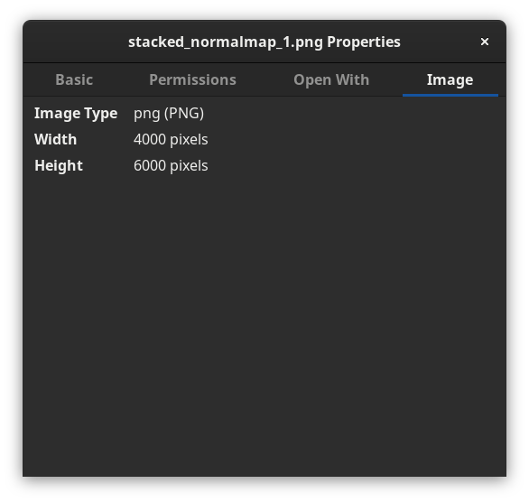
1) All images should be of the same dimension. This sounds trivial but depending on the focus-merging software and settings, image dimensions can vary from image to image by a few pixels. If it is not possible to get the input images to be of the same size, you have to account for that later – depending on the images and the overlap it is possible that you will not get good results.
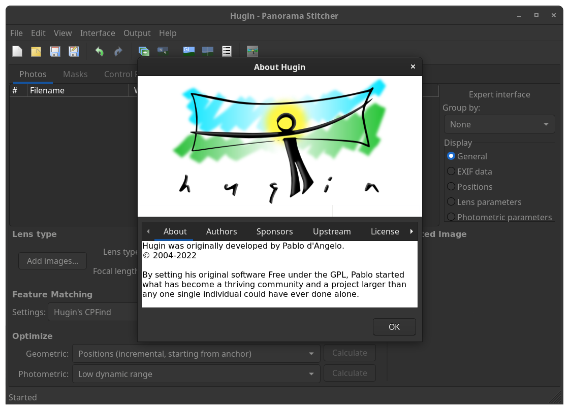
2) Make sure you have at least the 2022 version of Hugin (available as a flatpak). Under Interface in the top menu select Expert (you will need the expert settings later on).
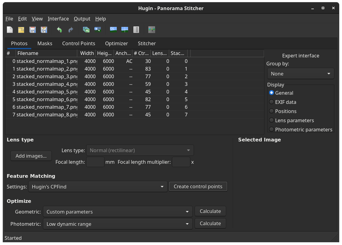
3) Navigate to the Photos tab (if you are not already there).
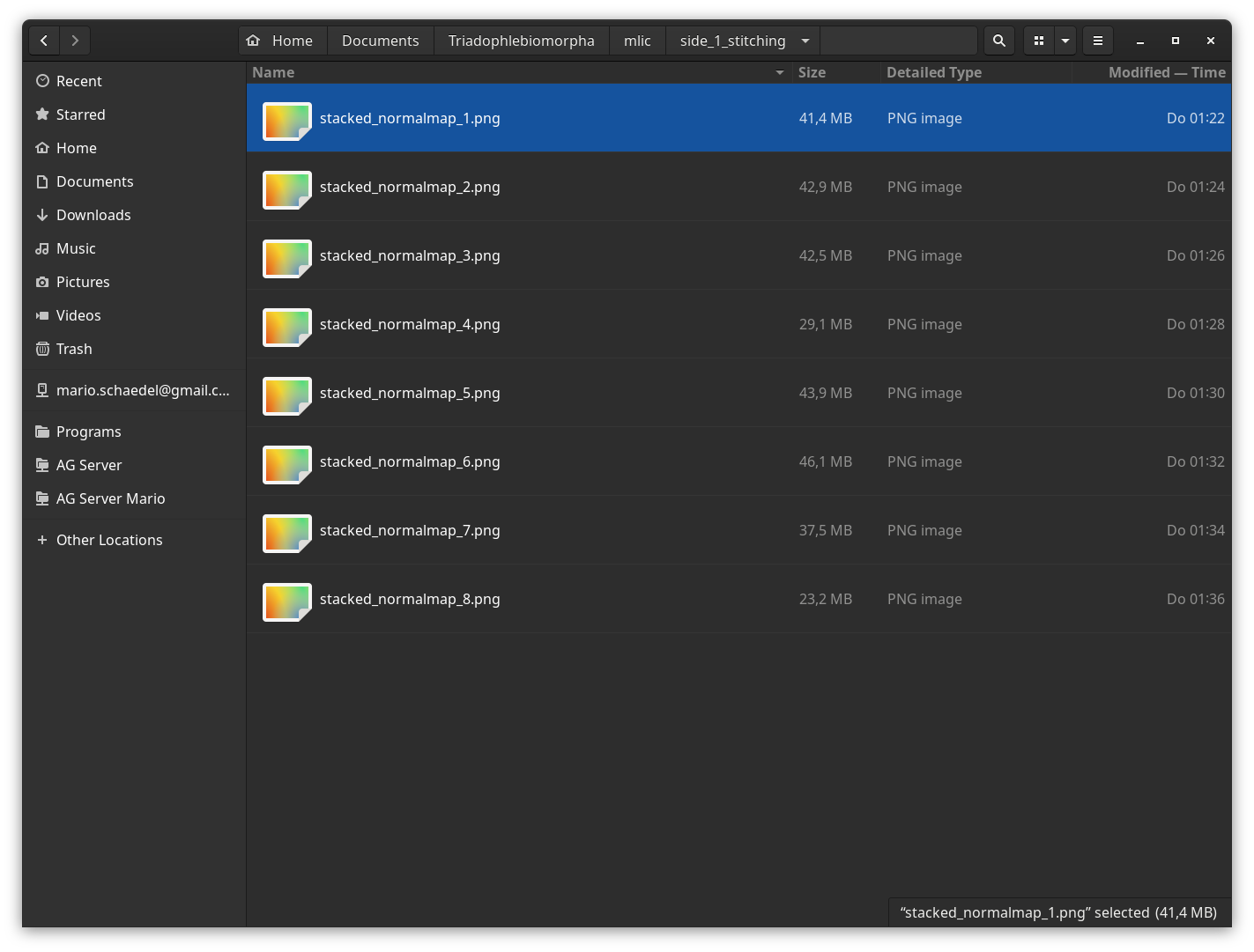
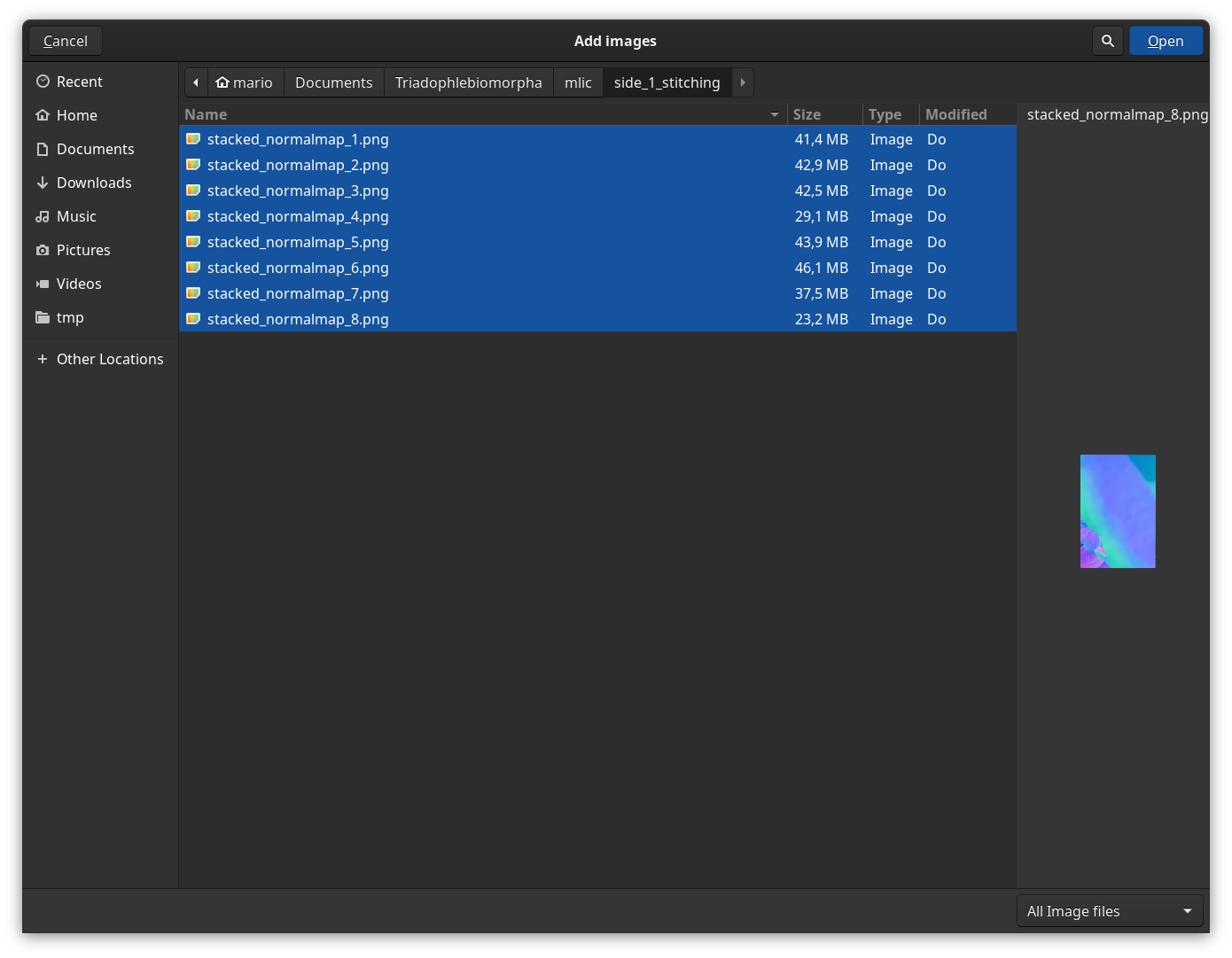
4) Import your images by clicking the Add images... button and selecting all images that should contribute to the panorama.
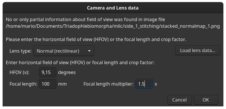
5) Enter your camera and lens data. For the camera data you have to enter the crop factor of the camera sensor (relative to a full frame sensor), so for example 1.5 for a Nikon DX (APS-C) sensor. Note that this will change the HFOV (Horizontal Field Of View) value.
If you could not determine the focal length, e.g. because you did not use a standard lens or lost the information which lens you used, click Cancel and it will fill in default values, which can be very detrimental for your stitching results if not recalculated later (see below).
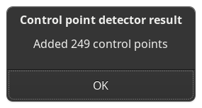
6) Under Feature matching click Create control points. Use the default option ‘Hugin’s CPFind’. You can inspect and manually edit the control points under the Control Points tab (useful for blurry images or images with large out of focus areas).
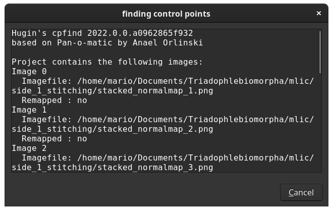
Check the number of control points and get a feeling for it.
7) Under Optimize select Custom parameters. Note that a new tab Optimzer appears.
8) Go to the the tab Optimzer.
Under Image orientation:
- Leave one image totally unchecked (Anchor image from the
Photostab, its position does not need to be optimzed) - For all other images select only
X(TrX)andY(TrY)to be optimized. This is unless you need to account for (accidental) tilting that might have occurred while capturing (e.g. handheld camera, movement of the specimen by hand leading to rotation)
Under Lens Parameters check a and b. If you were not able to determine the focal length then you also need to check Hfov (v).
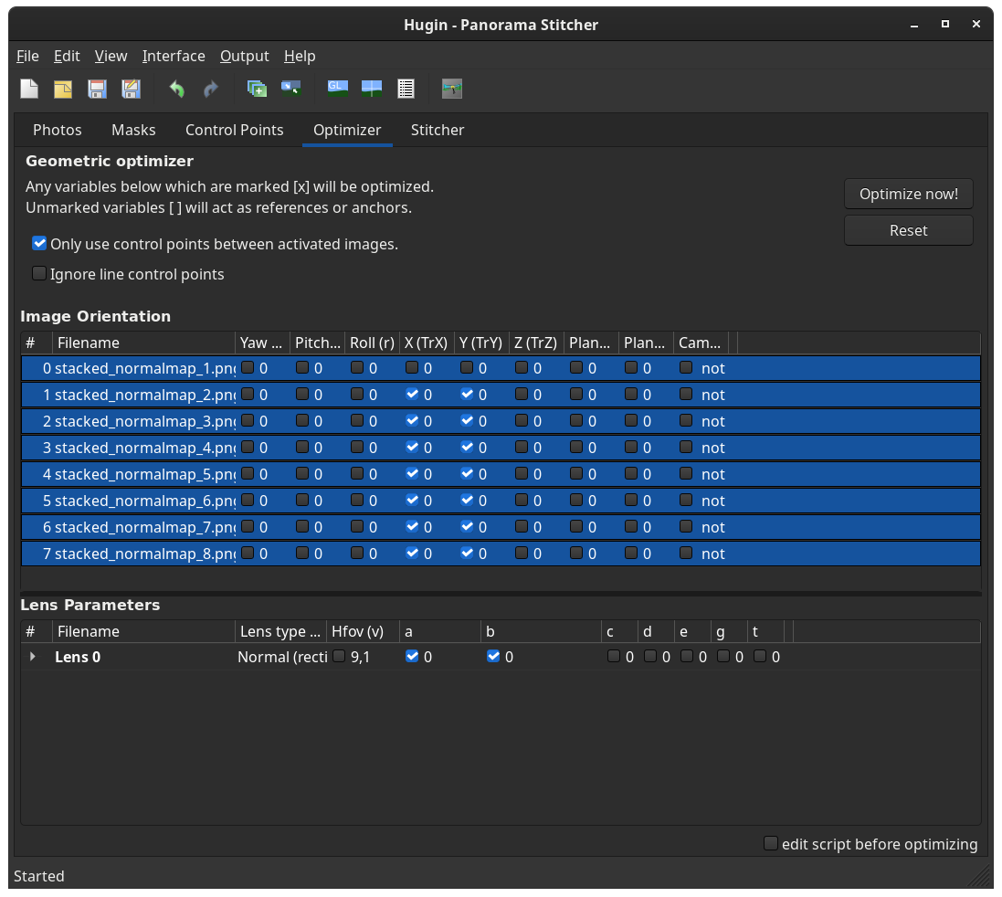
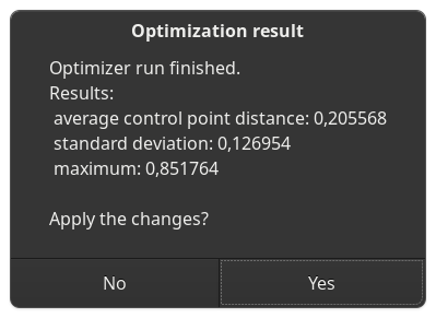
9) Click Optimize now!. The checked box Only use control points between activated images refers to settings from a different menu (all images are activated by default).
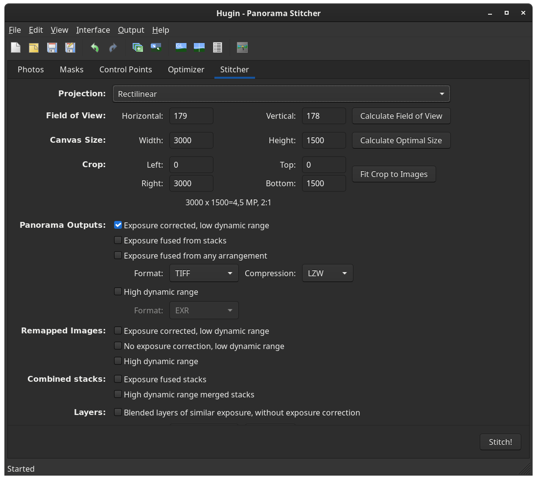
10) Go to the Stitcher tab and select the Projection to Rectilinear.
11) You can inspect your unblended stitching results now by clicking the iconized button Preview panorama or Preview panorama (OpenGL). This will open another window with the Simple interface. Use the sliders and the mouse wheel to zoom in and out.
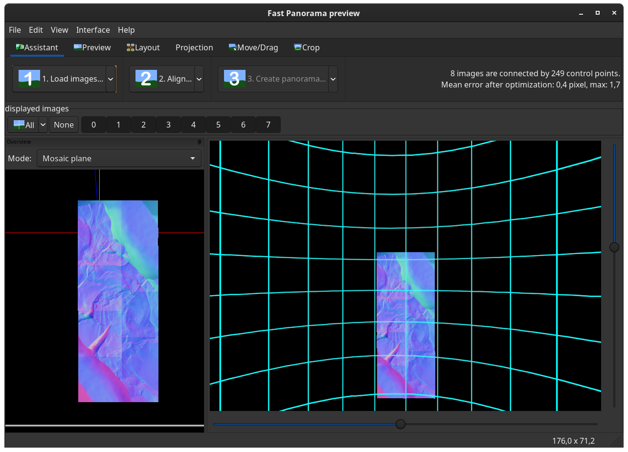
12) Go back to the Stitcher tab and click the buttons Calcuate Field of View and Calculate Optimal Size. You may also click Fit Crop to Images. This will remove unoccupied image space; yet, it can also cut off areas of your panorama that stick out from a rectangluar arrangement. You can always crop the image later in a raster graphics editor like GIMP.
You can leave all remainder settings at their default values.
Click Stitch!

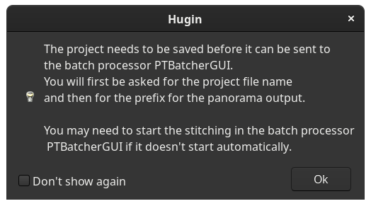
13) Before Hugin blends together your panorama, you need to save the stitching project, so that the command line programs that do the heavy lifting can read the information they require.
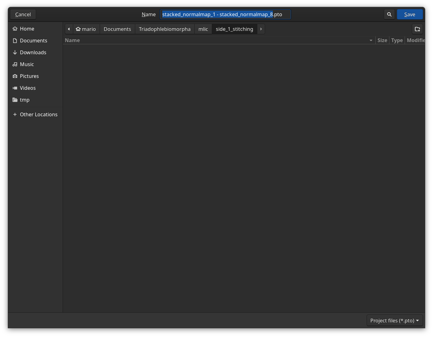
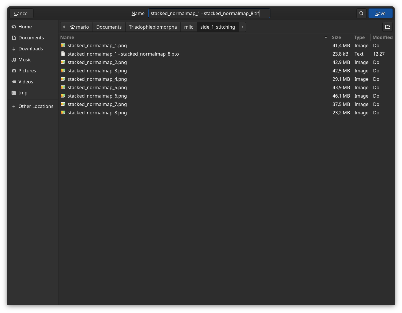
14) You will also be asked to provide a file name. Make sure to also append the desired file extension (.tif for the default Stitcher settings)
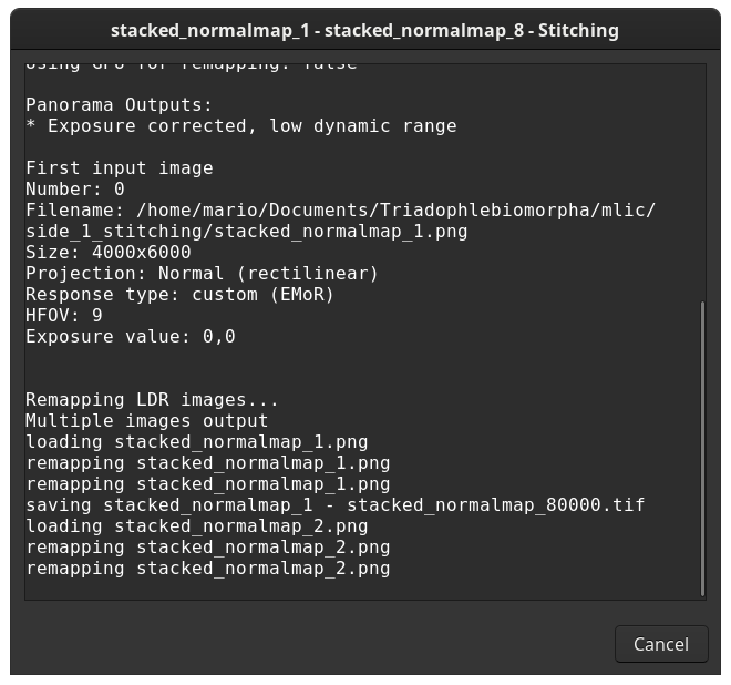
15) Hugin will then try to run your project and constantly tell you what it is currrently doing. Hugin may also open another where your project will appear as one job in a batch processing queue. Ignore the batch processing window – do not close it!
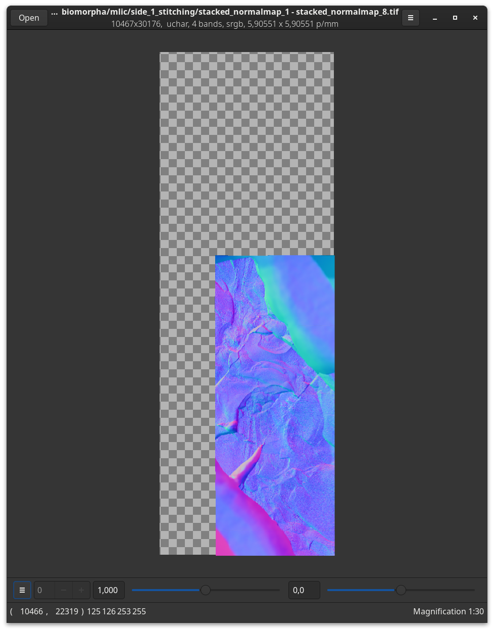
16) Note that the resulting panoramic images, especially when not automatically cropped, can have very large pixel dimensions. Because of this, it may be best to either use a powerful raster graphics editor like GIMP to open it and to crop it to the desired dimensions or to use a image viewer that is designed for large images like vipsdisp to open it.